Electromechanical Energy Conversion: What is It?
Electromechanical Energy Conversion
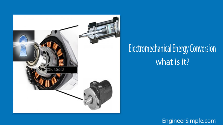
Electromechanical energy conversion (EMEC) explains how electrical energy is converted into mechanical energy or vice versa. The explanation includes the basic principle of this conversion which is based on the universal law of energy conversion. It states that energy can not be created or destroyed. It can only be transformed from one form into another. The device that converts one form of energy into another is called an electromechanical energy conversion device (EMECD). It is also popularly known as the coupling field.
For example, if there is a device that converts electrical energy into mechanical energy or vice versa. It is placed just as shown in the figure. The device that converts energy from electrical to mechanical is shown in the figure as a motor. The other one which converts mechanical energy into electrical energy is called a generator. Therefore, the EMEC device depends upon the input and output of the energize.
Now let's come to the coupling field reaction. When the motor is used as a coupling device, motoring mode is on. Electrical energy is in the input section. Thus current flows through the motor which is ideally considered a lossless device. In that case, complete electrical energy is converted into complete mechanical energy. However, in practical cases, these lossless coupling fields store some energy in a form of a magnetic field. Hence, it will not be a lossless coupling field. The electrical energy is then converted into rotational force through the shaft connecting to the motor. This rotational force is known as torque. In the end, it gives the mechanical output. When the generator works as the coupling device this phenomenon is just reversed. Therefore, mechanical energy is converted through the generator into electrical energy.
Now let's discuss the energy flow diagram of EMECD. We already know that input is electrical energy and output is mechanical energy for a motor. Let's see what is happening in between these energies which are described by the energy flow diagram. When electrical energy is fed to the motor, it is called gross electrical input. After that losses are incurred in the system known as electrical losses. Common losses are copper loss and core loss. Copper losses are popularly denoted as variable losses and core losses are categorized as hysteresis and eddy current loss. After calculating the losses, the resultant is called net electrical input. This input is fed to the coupling field reaction where some losses are also associated. These losses are called coupling field losses. After that, the resultant is the gross mechanical output which produces mechanical energy. But like the input section, some losses also occurred in this portion. These losses are called friction losses and windage losses. After taking this into consideration, the final output known as the net mechanical output is delivered as mechanical energy. Likewise, the motor and the energy flow diagram of the generator are just opposite.
The law associated with this topic is the law of magnetism. Three important definitions need to be understood for this. Magnetic field, magnetic flux, and magnetic flux density.
The area in which the magnetic force is experienced is called the magnetic field.
The amount of magnetic field produced by a magnetic source is known as magnetic flux.
And the magnetic flux per unit area is called magnetic flux density.
Whenever electric current flows through a conductor, there exists a magnetic field whose direction is indicated by the thumb of the right hand. It is called Fleming's right-hand rule. The principle of the motor is based on this.
Application of electromechanical devices:
First category devices: low energy signals into electrical- telephone receivers, microphones, speakers, transducers.
Second category devices: Force and torque production- Relays, circuit breakers (MCB).
Third category devices: Continuous energy conversion process- Motors, Generators.


.png)

